This guide is intended to be an organic document, as new information, parts, tricks, pictures etc become available I plan to update and change the document.
Let's start off with the parts you will need:
(The prices shown reflect MSRP as of 6/29/11, generally online parts retailers offer them at 20-25% below list price)
Timing Belt ...................5142579AA - $209
Tensioner Pulley ..............5142798AA - $126
Idler pulley (2 required) .....5142573AA - $62.75
Timing cover gasket ...........5066921AA - $18.75
Water pump ....................5142985AA - $267
Water pump O ring .............5159019AA - $6.25
Water pump gasket ...............4864575 - $3.60
Thermostat ....................5142601AA - $146
Thermostat gasket .............5066806AA - $2.85
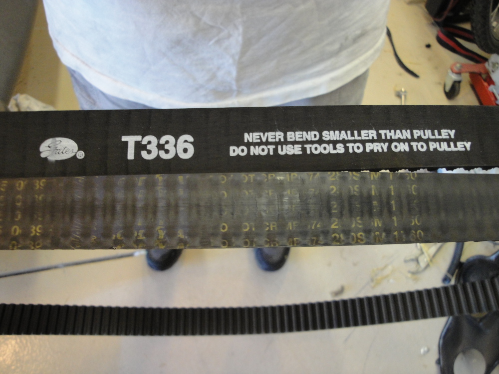
Now there are alternatives. When I did my parts I ordered a Gates timing belt for about $85 from rockauto.com, and at the same time I replaced the serpentine belt with a gates belt.
My recommendation for the 100k service is to NOT replace the water pump, but replace the Timing Belt, Timing Belt Idlers Pulleys, Serpentine Belt, and as much new coolant as you can get it to take.
My recommendation for the 200k service is to replace the belt, pulleys, water pump, timing belt tensioner, serpentine belt, and as much new coolant as you can get it to take.
Now onto the procedure:
These are the basic steps to follow, I will discuss the details below.
1. Remove stuff in the way(fan shroud, radiator, whatever it takes)
2. Remove mechanical Fan.
3. Remove Serpentine Belt.
4. Remove Mechanical Fan pulley/mount.
5. Remove Serpentine Belt Auto tensioner.
6. Remove crank pulley.
7. Remove front cover.
8. Install cam lock pins/crank lock pin/cam locking tool.
9. Add alignment marks on the crank, injection pump, and cam gears for safeties sake and to insure the CP3 injection pump stays timed correctly.
10. Loosen TB belt pulley tensioner bolt.
11. Use tensioner tool to back the tension off of the belt.
12. Remove Belt.
13. Install new belt.
14. Reverse of removal.
Now that being said here is the nitty gritty, the stuff you need to know to get it done, the above steps make it seem pretty easy, but its not, and the devil is in the details, its the little tips and tricks that make it easy or hard. Skip down a little bit if your already torn down to the point of the timing belt, the first part of this document deals with how to get to the timing belt.
Let me preface this by saying that I had extreme difficulty removing the mechanical fan from the idler pulley. If you were able to remove the fun nut from the pulley with everything else in place then removal of much of the front end would not be necessary.
To remove the mechanical fan you will either need a large crescent or 36mm(IIRC) wrench. Since the pulley can rotate freely you will need to hold it to get it loose. This is where I ran into trouble.
I tried so many different things but nothing worked and with the limited clearance with everything in place I had a hard time trying new things. One thing that showed the most promise, but I was unable to get to work, was to use a deep socket through a hole in the idler pulley to catch on one of the bolts that holds the idler pulley to the engine.
On the drivers side almost directly at 3 o'clock is the bolt that I am referring to. If you can get a deep socket in there that may be able to hold it(If not there are a couple of other options).
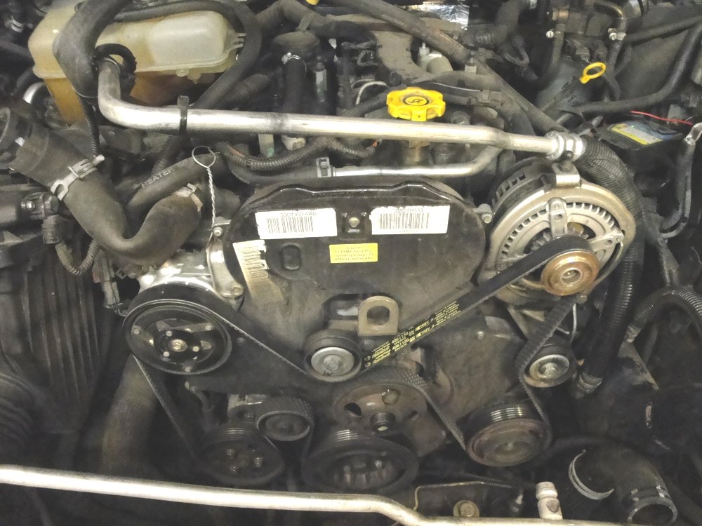
If you look at this picture you will see the pulley without the mechanical fan on it. The hole in the pulley at the 3 o'clock position is where one of the bolts is that holds the pulley idler on. That is the bolt I would recommend getting a socket onto to hold the pulley in place.
An adjustable pin spanner would work nicely, if you can find one.
tjkj2002 posted something that seems like it would work nicely if you had an air hammer, probably a specific enough of a tool that most of us don't have it:

What I did end up being able to use was a 3 foot long screwdriver that I stuck into one of the holes on the idler pulley and braced against the passenger side frame-rail. Then with my large crescent I was able to break the thing loose finally. But to do that I needed to get crap out of the way.
The way that I did it was to remove the upper radiator support, and set it aside(with the hood latch and cable still connected). Then I removed the grill, followed by the header panel with lights and all. To remove the header panel you will need to remove the front bumper cover. I will leave it up to you to figure out the details and just leave you with these comments:
The upper rad support has 2 bolt on the right side, 2 on the left, and 2 in the middle down low on the bumper support. The Grill comes off with little plastic tabs that attach to the header panel along the top.
The header panel has a bolt on either side by the two for the upper radiator support, it has a bolt on either side by the foglight that the bumper attaches to. And then it had a bolt on either side below that that is hidden by the bumper cover.
Now, with either that crap out of the way or if you are able to get the fan off with greater ease than me heres how to proceed:
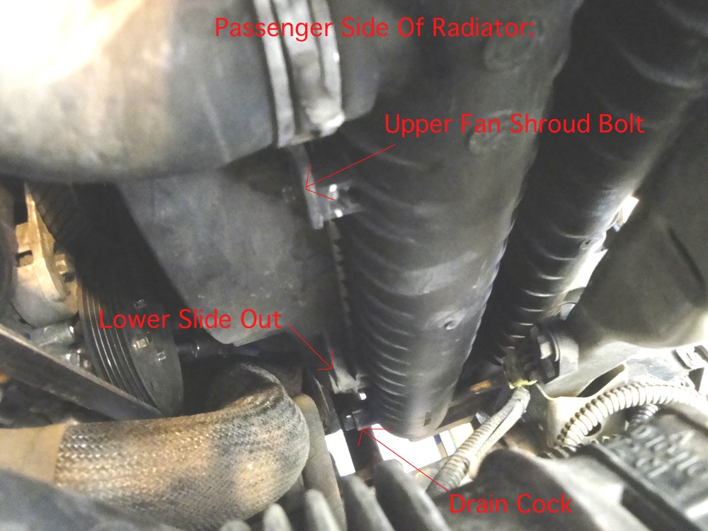
Drain the coolant via the draincock on the radiator.
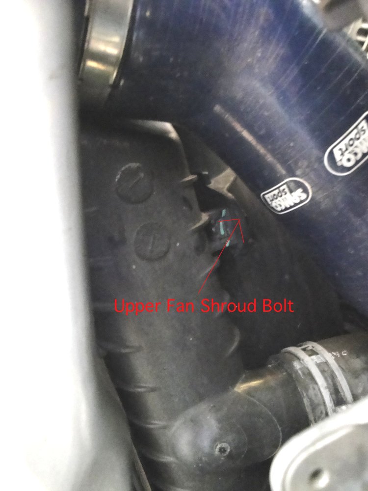
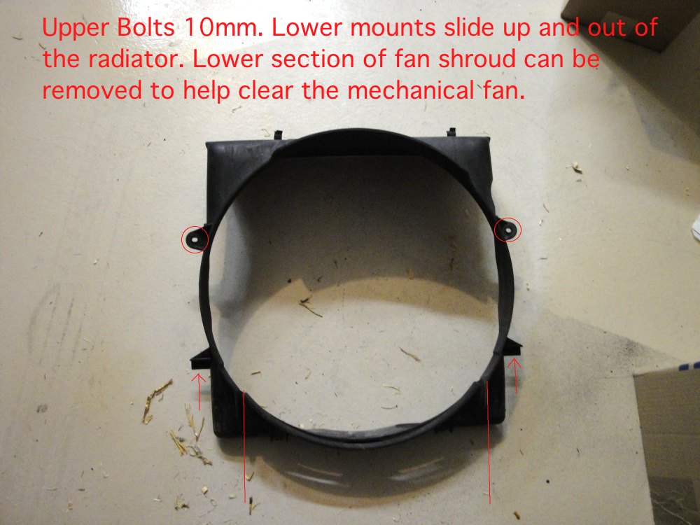
The fan shroud is held on with two bolts, one on either side, and then there is a tab on the bottom that slides onto a holder on the radiator. With the 10mm bolts removed the fan shroud will then just pull up. If you are able to remove the mechanical fan it should pull out at the same time as the fan shroud to give you access.
You can see one of the bolts to remove the fan shroud here, its twin is on the drivers side:
And the drivers side:
With the fan and shroud out of the way you will need to remove the serpentine belt.
With the serpentine belt out of the way you will need to remove the two belt idlers and the belt tensioner. A note of caution, the two serpentine belt idlers have reverse rotation threads. The crank pulley is hold on with 4 bolts and then removes without the need of a puller. The main crank nut DOES NOT need to come off, only the 4 bolts. The fan idler pulley will need to be removed, one of the bolts is hidden behind the pulley and will need to be accessed through one of the pulley holes.
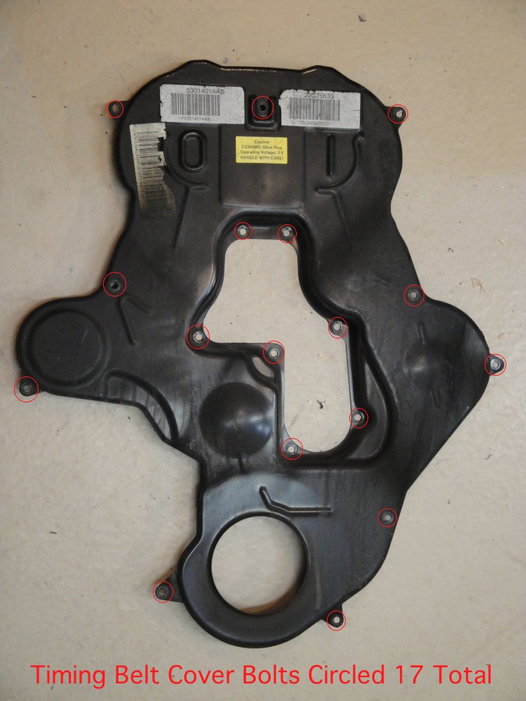
With the tensioners, idlers, and crank pulley removed its time to remove the front cover. 17 bolts, 8mm(IIRC) hold the cover on. Have fun with all those.
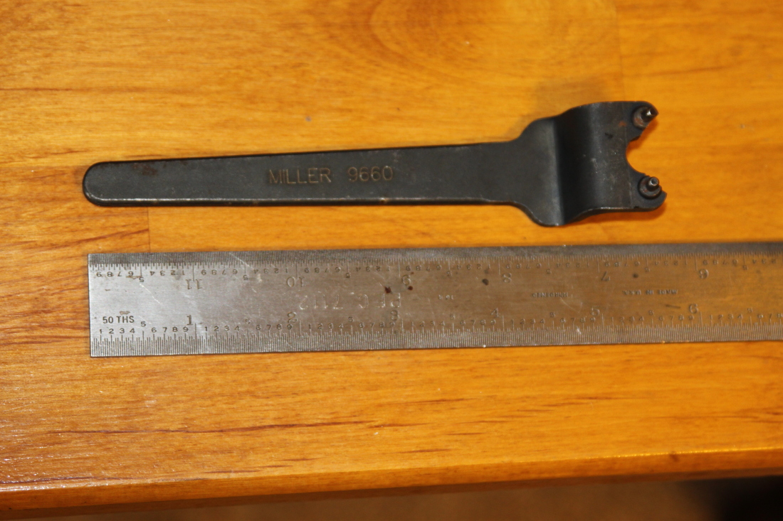
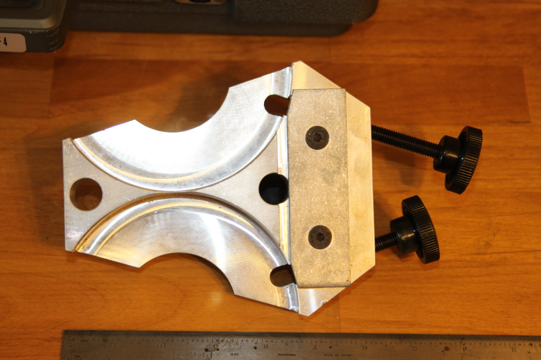
The miller tools for the Timing Belt job:
This is the tool for adjusting the TB tensioner: (miller 9660)
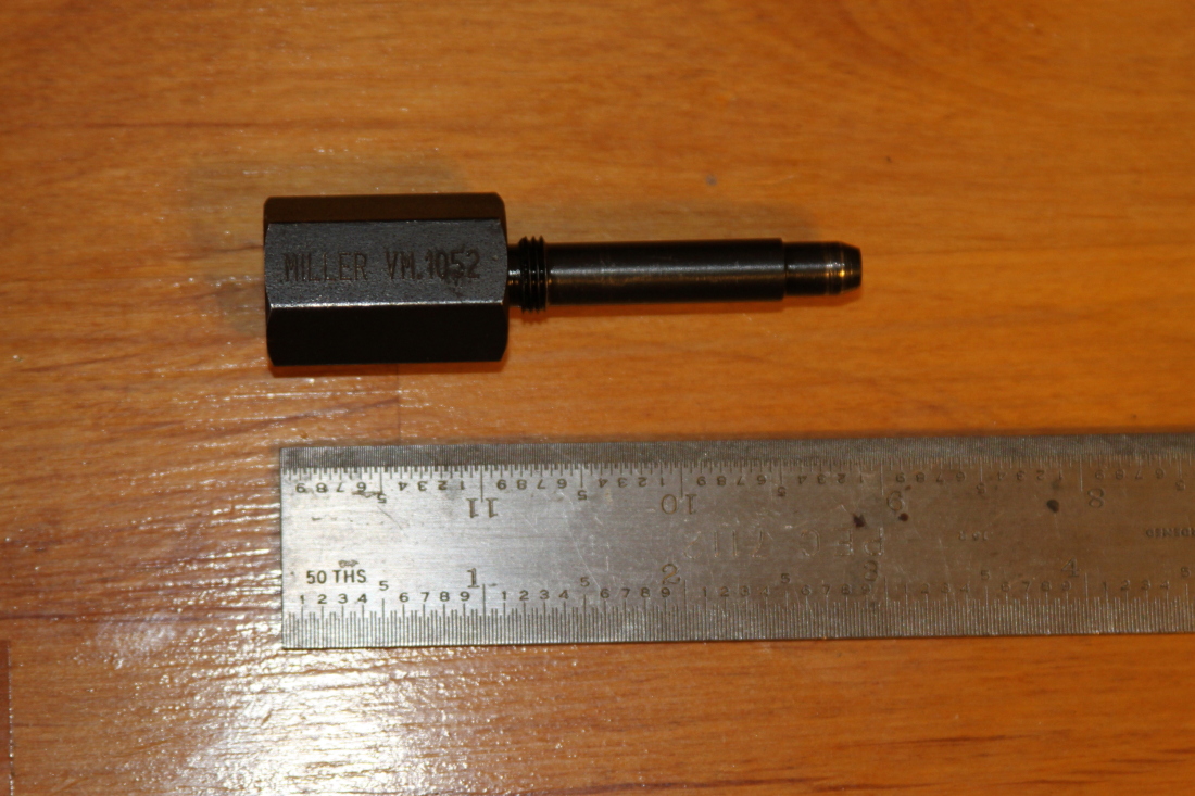
This is the Intake cam locking tool: (Miller 1052)
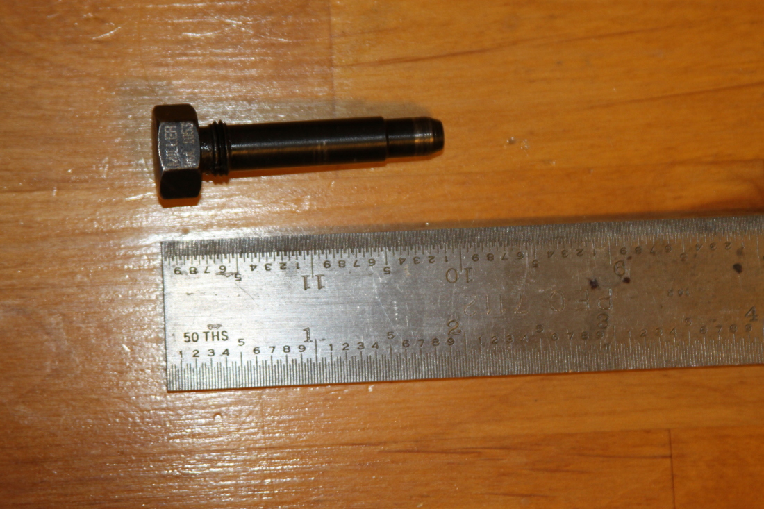
This is the Exhaust cam locking tool: (Miller 1052)
This is the crank locking tool: (Miller 1089)

This is the cam gear locking tool: (Miller 1085)
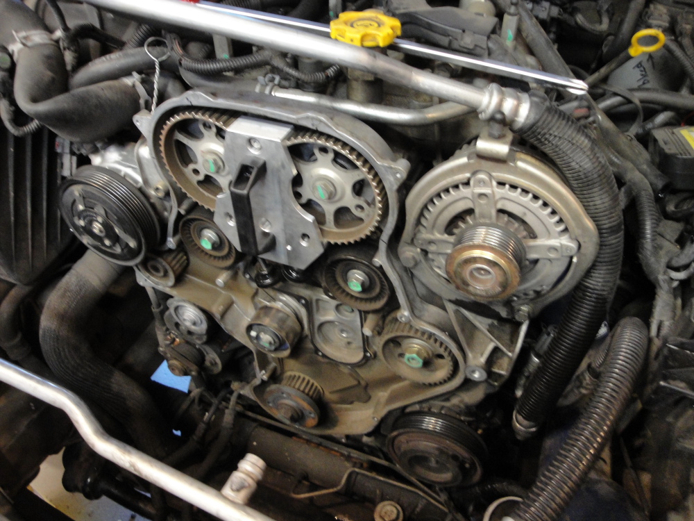
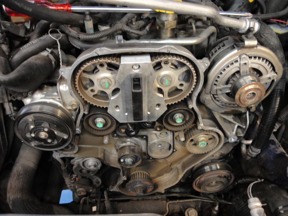
Timing belt specifics: With the cover off you can now think about removing the Timing Belt. There are several ways to go about this:
A) You have none of the specific tools.
B) You have the camshaft pin tools, and the gear holder tool.
If you are person A then you should only attempt to replace the belt, idlers, and tensioner.
If you are person B then you can also do the water pump. If you do not have the miller tools, specifically the gear holder, DO NOT attempt to replace the water pump.
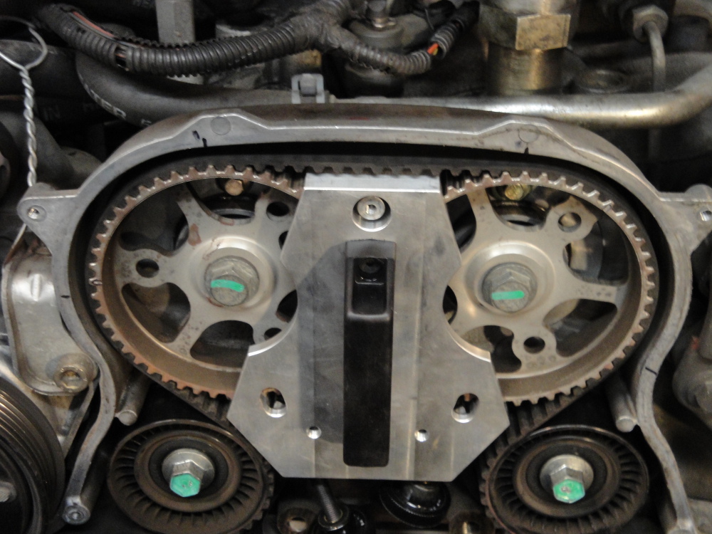
Let me explain the use of the tools a bit. The cam locking pins will lock the cams at 90° aTDC. The crank locking pin will lock the crank at 90° aTDC. The gear holder will lock the cams relative to each other, the gear holder also is used when the camshaft pulley gears are removed for retorquing the retaining nut(as is needed when the water pump is replaced).
So if you are just doing a belt the gear holder is a very nice tool to use to lock the cams in the correct place during a change. The gear holder will not lock the crank in place, be sure to mark crank and the cams with a sharpie or other marking device before removing the belt!
The camshaft locking pins thread into the valve cover and the tip of them go into a small hole on each camshaft. These pins are meant to correctly time the cams to the crank. On the engine block, above the oil filter, there is a hole that is meant to align with the flexplate/flywheel at the same time. All of these holes will align at 90° aTDC (Ninety Degrees after Top Dead Center). It is possible to install the cam locking pins at 270° aTDC, and it is possible to accidentally install the crank pin through a normal flexplate hole. This makes retiming an engine an exercise in quadruple checking the timing before assembly.
However, we are not retiming an engine, as long as you don't have a slipped or broken belt your timing is already correctly set. You need only add some marking on the camshaft gears and crank gear to make sure you retime the engine to the same position. I say again; be sure to mark crank and the cams with a sharpie or other marking device before removing the belt! There are witness marks on the crank gears - they do not line up with any marks on the rear timing cover. Pick a convenient place and add a mark to the crank and to the backing plate for both cam pulleys and the crank pulley.
So once again, if you are person A you can mark the gears, and remove and install the belt paying careful attention to the gear alignment without any special tools. It won't be the easiest way but there is no reason you can't do only the belt/idlers/tensioner without special tools.
If you are person B, you can do either the belt/idlers/tensioner, or the belt/idlers/tensioner/ AND water pump. If you only want to do the belt/idlers/tensioner then by all means install the cam locking pins, the camshaft gear holder, and mark the cam/crank gears.
If you do replace the water pump make sure to use the gear holder when reattaching the pulley, the camshaft locking pins cannot take the torque needed to lock the retaining nut for the cam pulley. The cam gears are a press fit - no groove or woodruff key times the gear to the cam. Only the torque of the press fit keeps this in place.
Also mark the CP3(injection pump) as well. There's been all sorts of talk about keeping the timing of the CP3 correct, all I will say its that its easy to keep it the same as you took it off, so why not leave it the way its been?
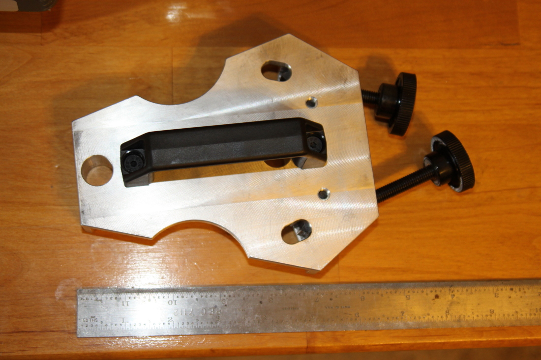
This is the VM tool to lock the cams in place, It is part of the complete Miller tool kit, which also includes locking pins(which would be redundant when using this tool for only the timing belt).
Please Note: Removal of the water pump requires removal of at least the exhaust cam pulley, in this case the VM cam locking tool pictured above cannot be used to lock the cams in place and the cam locking pins are necessary!
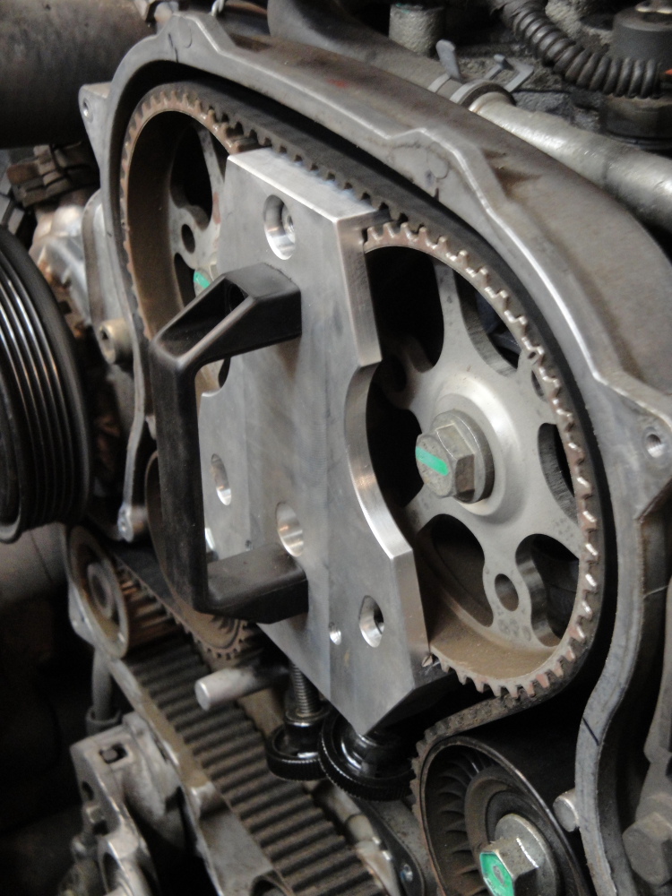
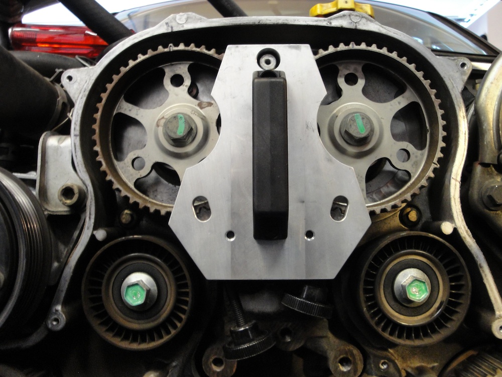
The VM locking tool has these threaded lockdown tools that engage into the teeth of the cam pulleys. Make sure they are fully inserted into place before releasing belt tension, you may need to rotate the engine by hand a little to make sure the locking point fully engages into a "valley" between the teeth.
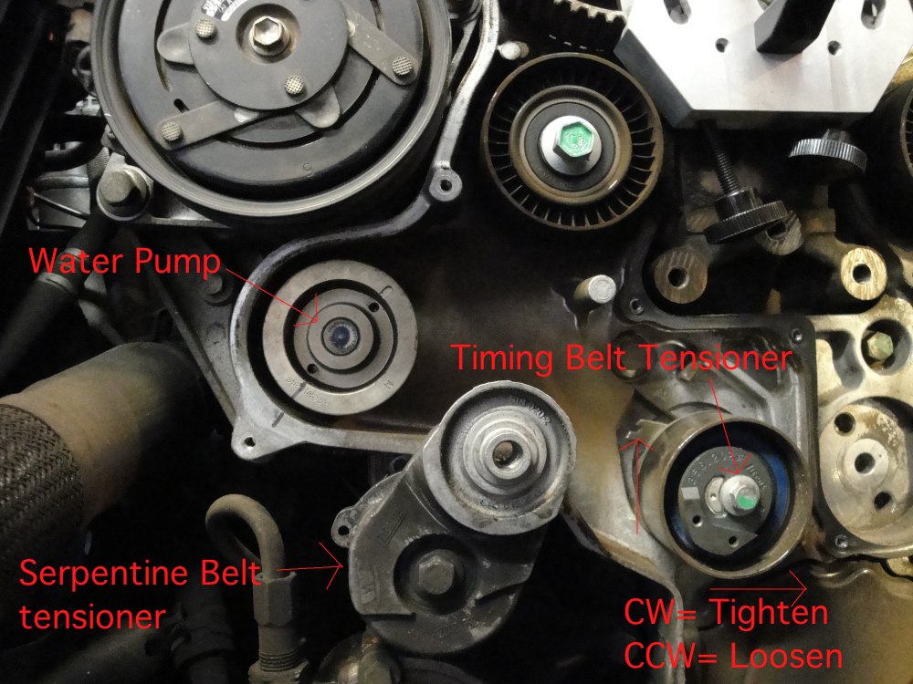
With everything locked down and marked you can remove the belt. You will need to loosen the tensioner, the bolt that holds it on also keeps it tight. I had (incorrectly) assumed that the tensioner was an auto tensioner, it is not. With the tensioner loosened use the VM tensioner tool and turn it CCW, this will take the tension off the belt. During reinstall turn it clockwise until the belt is tight and then set it in place with the bolt. With everything loose remove the belt.
When installing the belt make sure that all your marks are lined up correctly, turn the engine over by hand until all the marks line up again. I did this several times before I managed to get it right, turns out I kept installing it one notch off at the crank pulley. I ended up using a ratchet to turn the pulley CCW a little, get the belt on, and then turn it back a little CW. By doing this I was able to get the correct number of teeth between the CP3 and the crank. Having the one extra tooth between them made the belt impossible to slip on even with the tensioner completely loose. With the correct tooth count there the belt slipped on with the tensioner completely loose(though it was still a bit of a stretch).
So thats it for the belt info, worst part for me was fighting the mechanical fan and having to remove all the other crap.
The fan shroud bolts:
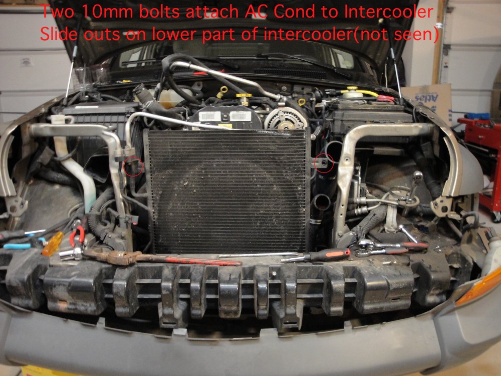
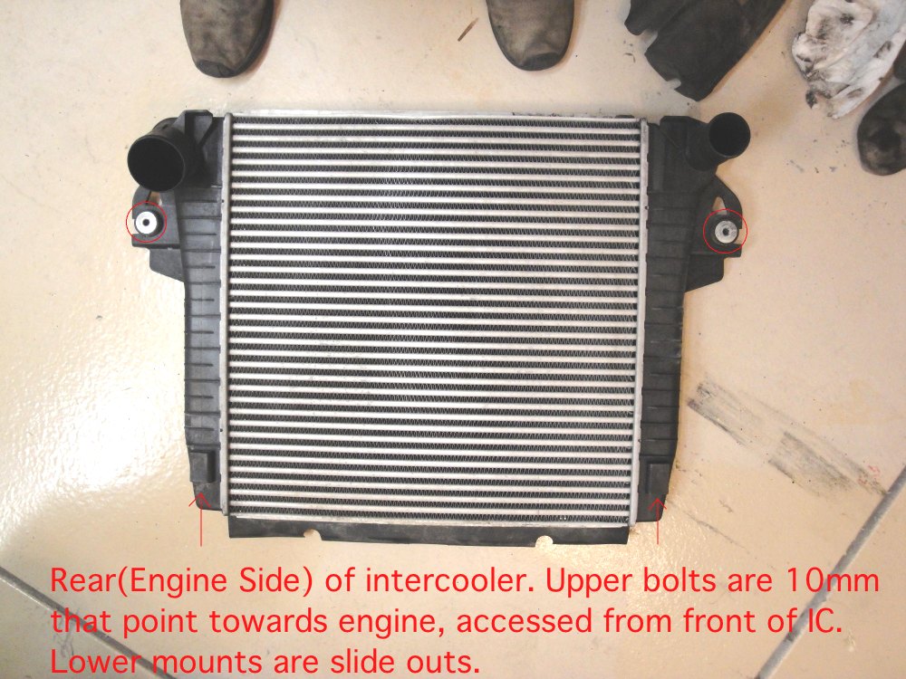
Intercooler/AC cond bolt holes:
Radiator side of Intercooler:
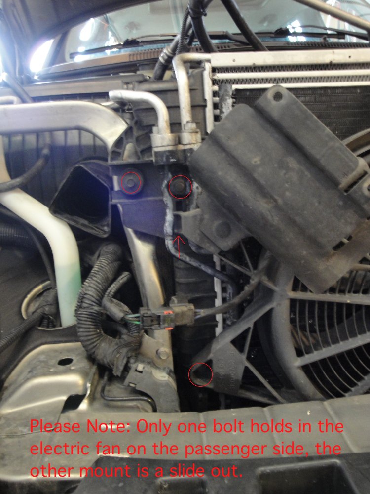
Fan shroud in vehicle:
Drivers side AC Cond bolts:
Passenger side AC Cond bolts:
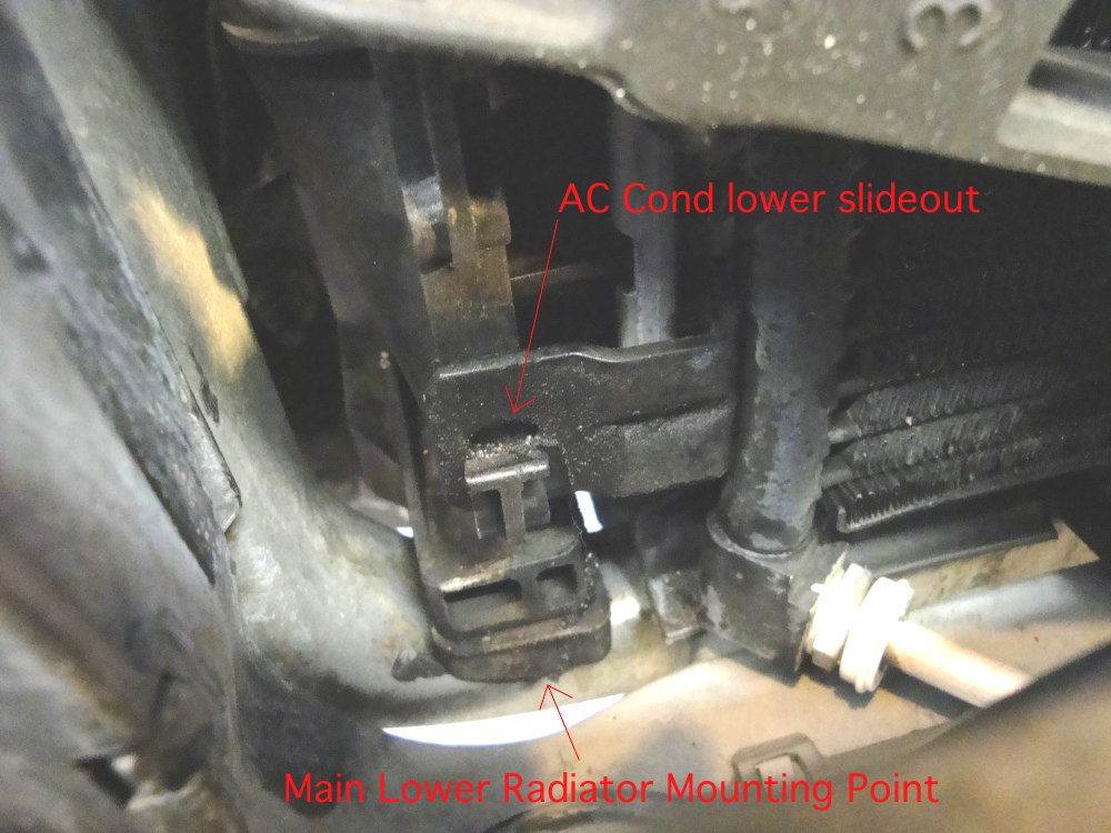
AC Cond slide outs:
This is the serpentine belt routing in case you're like me and forgot the instant you took it off:
Lets take a look at a used Timing Belt with 111k on it:
Surface wear:
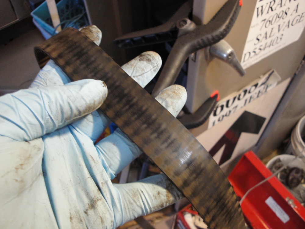
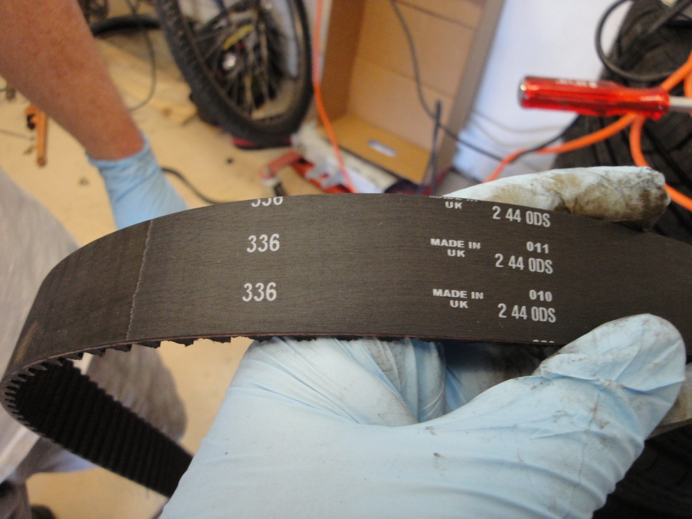
Underside looks better, but still is covered by the fine red dust that comes off the belt as is bends and flexes.

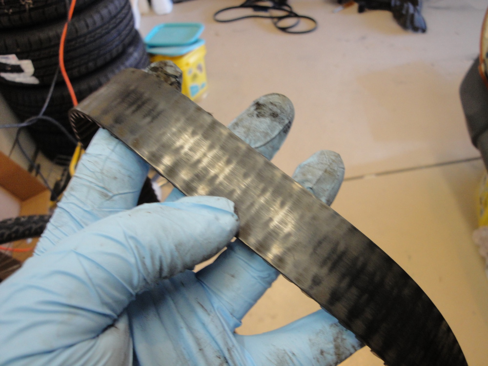
This is the new belt in comparison to the old, much less wear and it looks much better.
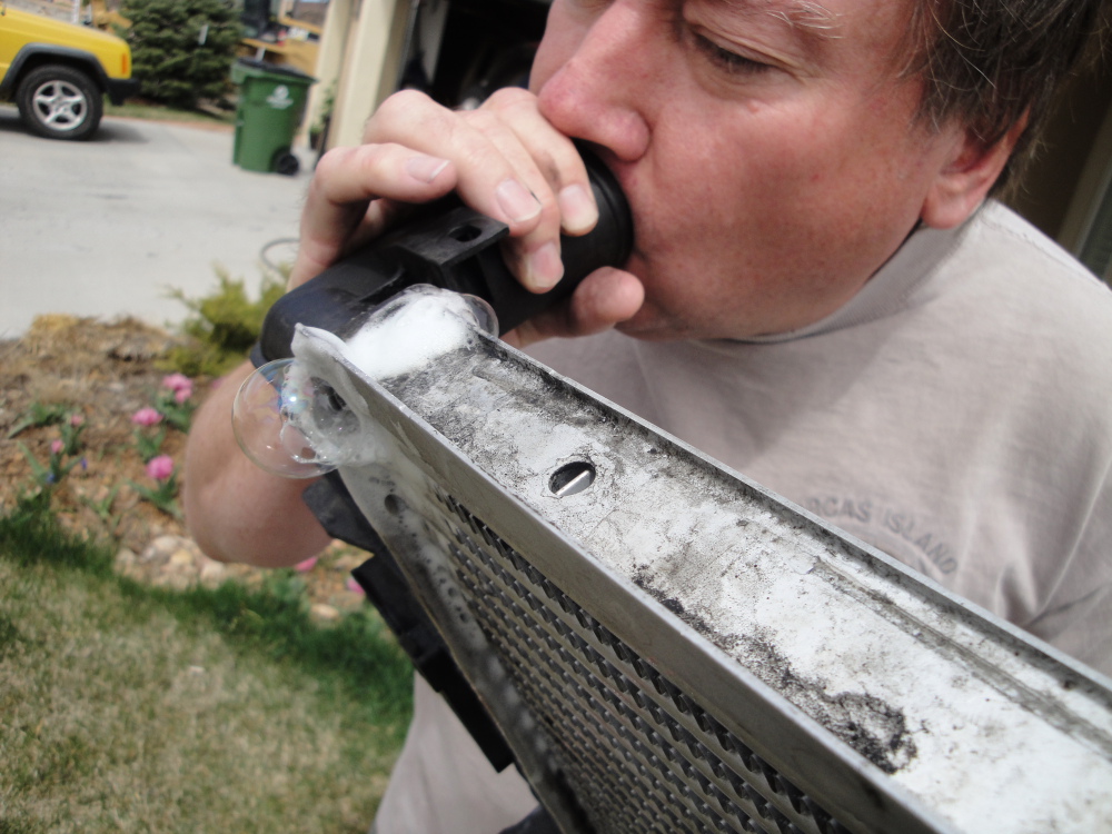
Pressure testing the intercooler:
With one hand over the outlet and my mouth firmly sealed to the inlet(No Jokes Please) I blew hard and could feel and hear some leakage, after making sure my mouth and hand seals where good I uses the old soap suds trick to find a location that was leaking.
So we got a little JB weld, mixed it up, and made it flow into the area in question(the top most tube on the inlet/hot side of the intercooler).
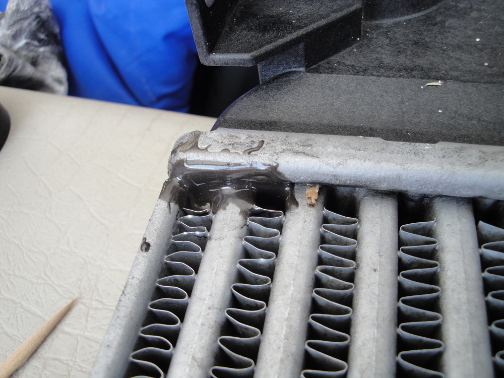
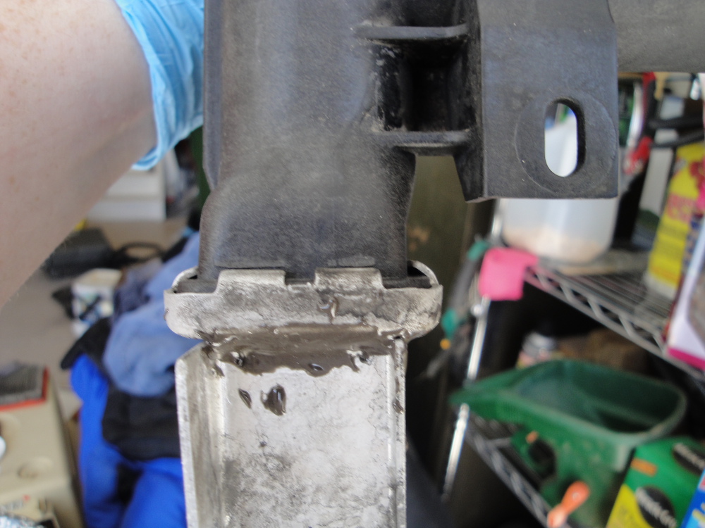

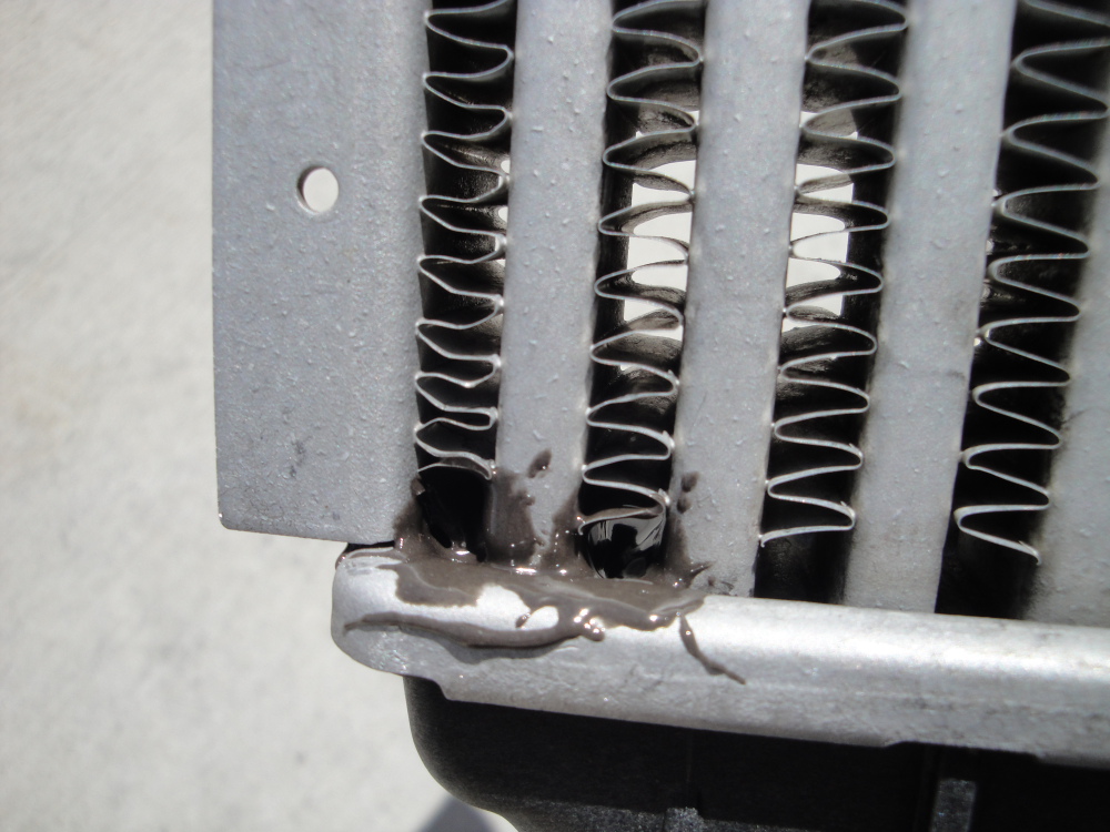
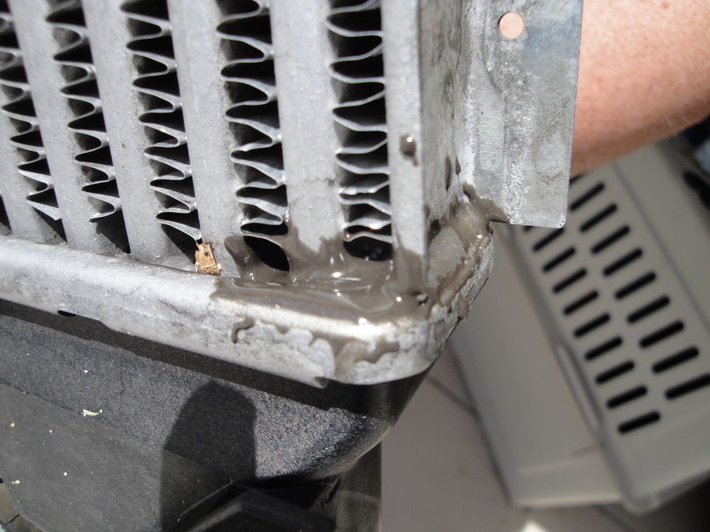
Problem solved! No more leaks from that location. During tear down there was a good buildup of oil on the IC near the leak, most likely oil from the intake pathway being blow out the small leak(right by the inlet) and covering the IC with a nasty oil buildup. If you see the same thing happening then you may be having a small IC leak like I was.
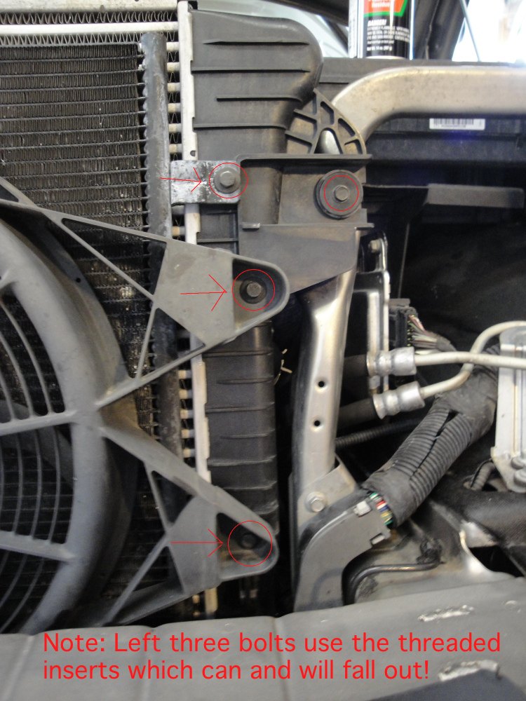
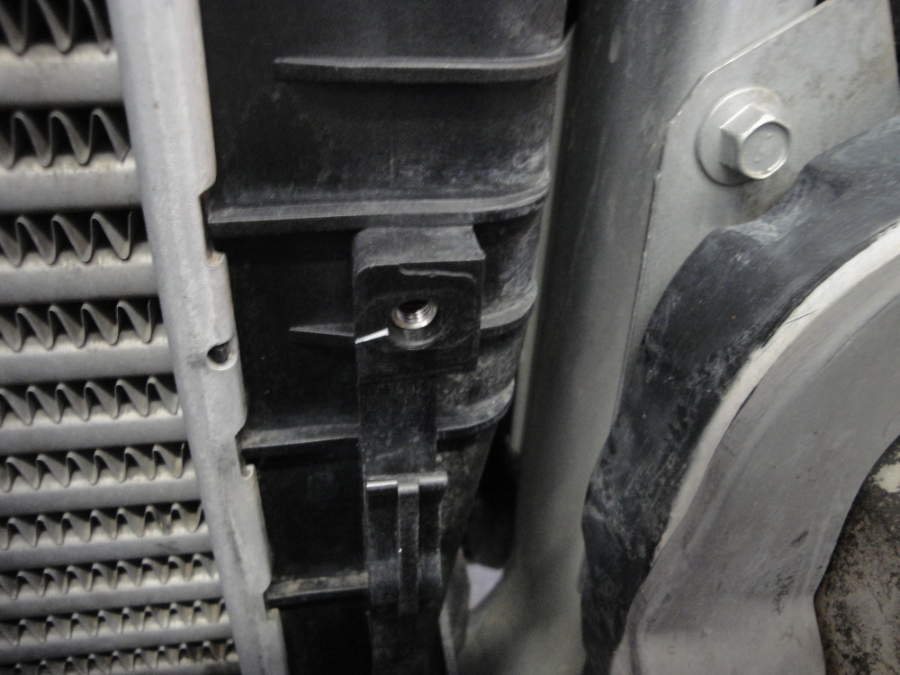
Do not loose these:
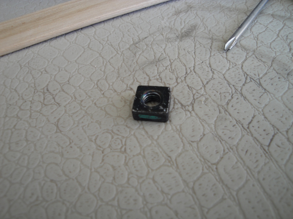
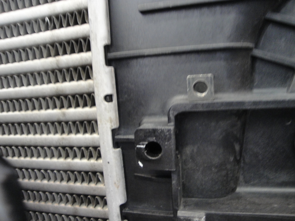
There are a bunch of these located all in the radiator and the IC. They are small threaded inserts that simply slide in to a plastic holder on the radiator or IC and let other things like the fan shroud and AC condenser bolt to them. I lost several and had to find some nuts that would work. I didn't even realize these could come out until I went to reassemble everything and found out I was missing them!
Example of one not missing:
And one thats missing:
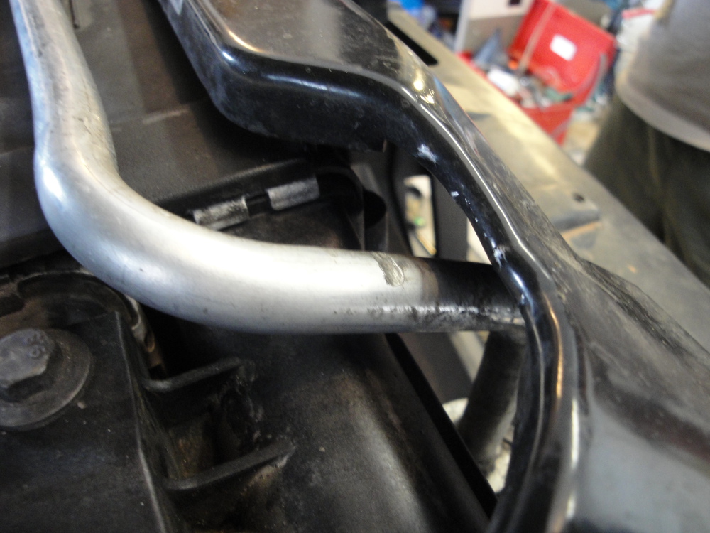
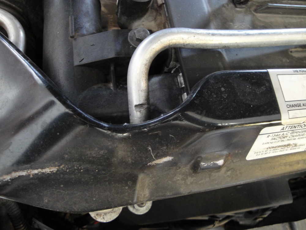
This was something I noted upon reinstall of every, the AC line had been hitting the upper radiator support, I bent the lip of the radiator support a bit and also bent the line down a bit, lots of clearance now!
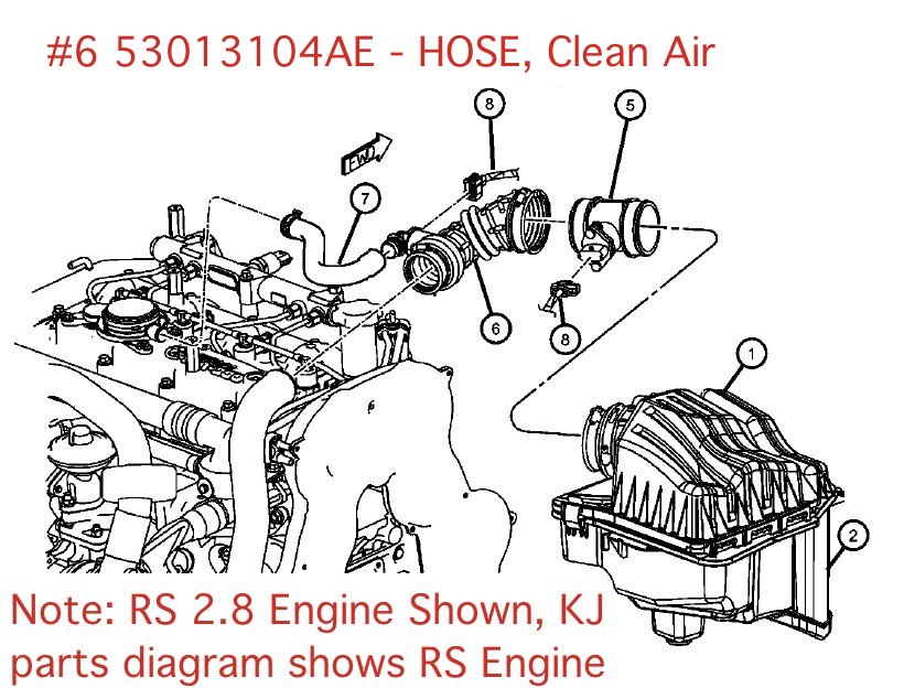
This is the turbo inlet hose. When I was putting everything back together I found out that the lower part where it clamps to the turbo inlet had degraded and ripped apart. I suspect it had been this way a while and only now I had discovered it. It appears that this will be a 100% failure item on most CRDs, mine has been running the EHM and ORM for the past 60-70k miles(since about 40k-50k on the odometer) and I still had this failure. The stock CCV system will increase this failure rate, yet another reason to run the EHM and ORM.
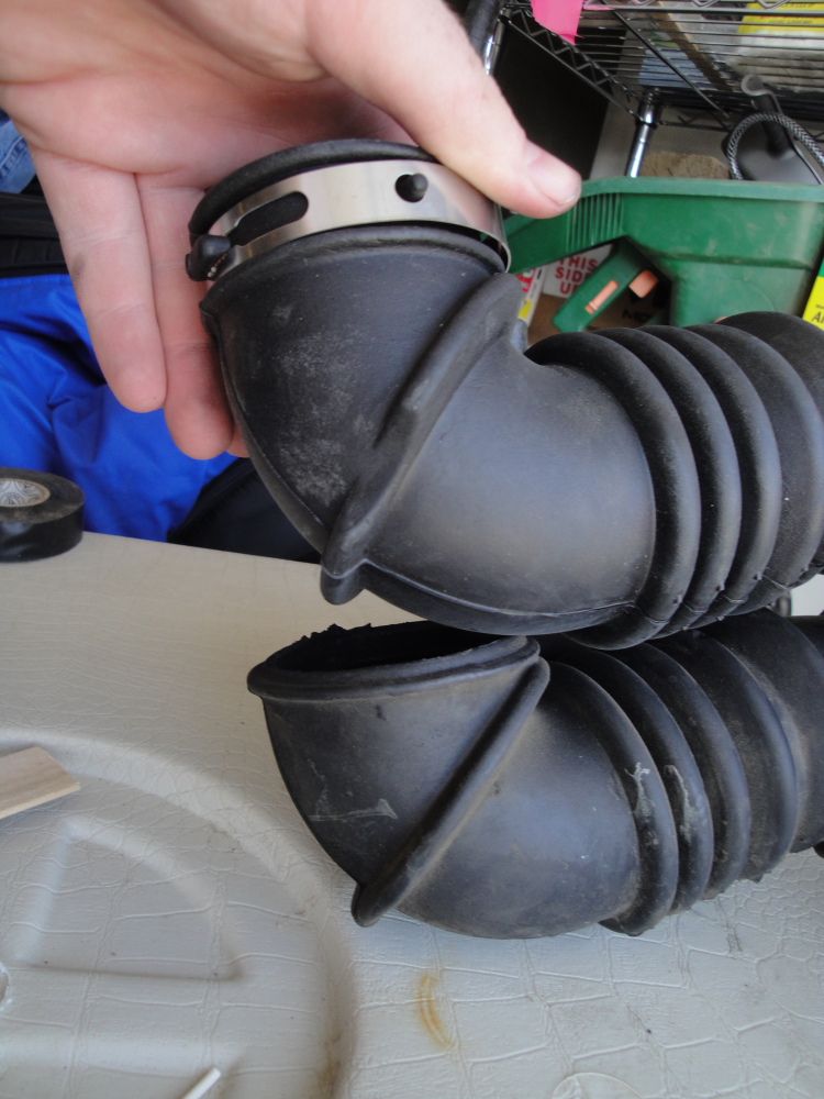
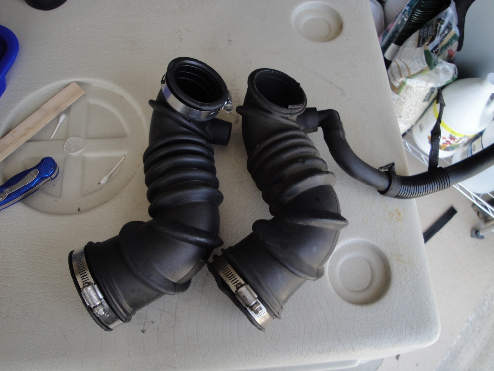
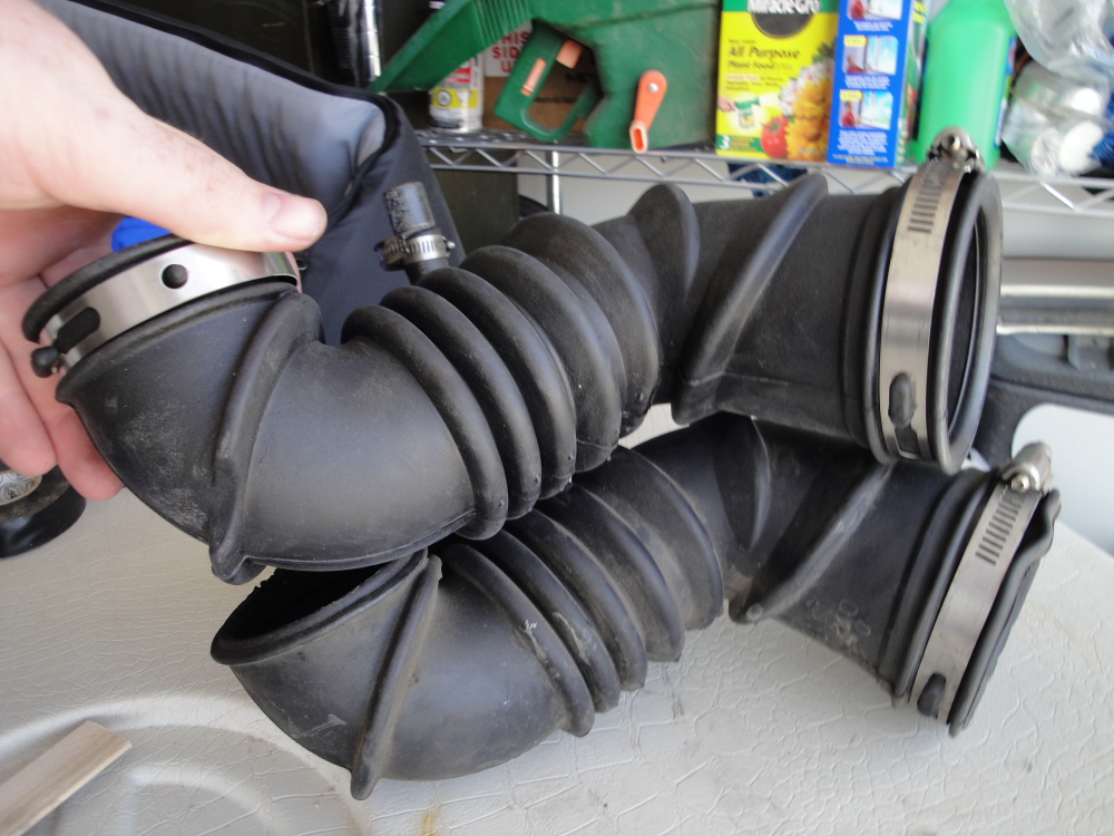
The Part number for the new part is 53013104AE - Hose, Clean Air: